My son wanted a closer look at the new pegboard.
Read More..
This post has been written by Vittorio, a friend of mine very skilled with hand tools. I only translate from Italian (hope not too badly) his great job. Thank you Vittorio and welcome to the blog! For some time I thought to build a metal plane and surfing the net I found a lot of ideas and this very good project:http://user.xmission.com/~jry/ww/tools/a13/a13.htmland my adventure started!
I thank you Jim Yehle from Salt Lake City, the author of the project from which my plane was inspired. I used Fe 430 steel. I think it is strong enough for good plane sturdiness and at same time permits to use hand tools for working it easily; I used 6 mm thick plate for the sole and a 5mm one for sides.
I started by coupling sides together, marking joints and boring for reducing the steel amount to be discarded; with patience I shaped the dovetails. These have 60° angles, as well as files have.
I cut the sole, marked out tails and sawn them as precisely as possible; this job was far more difficult.
Finally, the two sides are ready as well as a wooden support, useful for dovetail peening.
The iron holder comes from a 10 mm steel plate. It has a 47.5° angle and also is useful as support to the file for cutting the mouth back.
Side shaping, first lapping with 100 grit abrasive paper and 6mm rivet plugging in for blade holder fastening. 
The dovetail peening is the most important step; although the wooden support helps, it is important to control that the internal part of sides is square, to avoid troubles during plane assembling.
Cleaning up with a file and abrasive paper, until joints disappear and the sole is flat.
For making the lever cap I used template steel, a very strong material. I had to do more work for shaping it.
Handle and knob come from a 3mm thick well seasoned ash board; apparently working wood seems easier than shaping metal, but I spent several hours to obtain the right shapes.I used 8mm steel rods (bored in a machine shop) as spacers for handle fixing. Rods were threaded inside and inserted into the wood; as said above if the inner side is not square to the sole, the spacer ability of firmly holding the wood in place will be decreased. 
The wood has been finished with 8 coats of shellac, fixed to metal body with screws firmly screwed and then clinched. Unfortunately ordinary screws have the conical section too low, so the countersink has not completely filled. However the final lapping helps to attenuate the gap.
The blade comes from an old industrial cutter. It has been worked with glass paper for obtaining the 25° bevel and with 3M abrasives (40, 30, 15, 5, 1, 0.3 microns) for honing a 30° microbevel.Finally the road test. I tried the plane with fir, lime and beech. Its a pleasure use it. This is sufficient for satisfying me enough of the job, done only using hand tools.
The mouth opening is 1 mm. The plane weights 2260 gr.
Here is a pic of the polished infill plane. It is already at work.Final notes.
While I am waiting for a knurled screw for lever cap, I have done a wooden cap.Although the plane lacks of adjusting mechanism, its set up is easy.
The handle tail could appear too accentuate, but the grip results very ergonomic.
After all I am very happy beaucause has been a great experience with a good result.Ciao Vittorio
Read More..
This is my first post in my new blog.
My name is Donald and I am an amateur woodworker. I started this site to share my hobby with you and to document my learning process. I want this to be a place where you can come and see my thought process about how I made something and then hopefully add your two cents in. Im not going to be able to make a project every week but I will make as many projects as I can as often as I can.
Read More..
The date and location for Woodworking in America 2013 has been set. For anyone who didnt know:
The date was first teased on Twitter and confirmed on the Popular Woodworking Editors Blog the following day. It will be October 18th through 20th at the Northern Kentucky Convention Center in Covington, Kentucky (Greater Cincinnati). This is the same venue as WIA10, WIA11 and WIA12 MidWest. Ive been to them all, and its a great venue with nearby hotels, a $1.00 trolley and a Hofbruahaus. Ive alchoices had a good time there and Im sure you will too.
 |
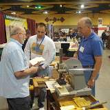
| WIA 2012 MidWest: We came, we saw, we posed on Megans bench. |
Im not such a fan of the piecemeal approach to announcements that has been used for WIA lately (if theres a date and venue, Id like a ticket), but at least we can all block out our calendars now.
Ill see you in Kentucky.
p.s. - Theres a White Castle. |
| Im at White Castle! |
 |
| MWA Woodworking in America 2012 Midwest Photo Sharing Event |
Read More..
Heres the latest video on the shop wall renovation. Not a whole lot of progress, but I did manage to finish the last of the electrical access panel frames.This last frame was the tricky one, incorporating a door to reach the electrical panel. Next up in the shop will be filling the 2nd layer of insulation around the electrical access and window frames.
Read More..
With the entire step stool now glued up I realized I hadnt cut feet yet. I took my Lee Valley Drawing Bow and marked out a subtle curve in the middle of each leg. Once I cut out the curve with a jig saw, it left two (2) feet on each leg.
 |
| All ready for feet. |
Now with feet I took the step stool over to my router table. After the nasty incident with my neighbor during this stage of my last project, I setup my router table inside this time.
I removed the fence and used a bearing guided ¼ radius roundover bit, I ran every reachable edge of the stool (except the bottom) over it. This method took a bit of getting used too. With a bit of practice I soon found it easy as the stool is not so big as to hang completely off the router table yet is big enough to provide plenty of reference and holding surface.
 |
| Its starting to look curved. |
Fresh off the router table the stool (or any piece having this roundover method used) is rounded, but not done. The routed curves on the edges are hard, disjointed and where they do flow into each other they have a shallow, machine cut look. I only use the router to hog off most of the waste, not to provide my final edges. After routing it is time for rasping.
 |
| My arsenal (and some additional). |
As Ive grown to enjoy the process and results of using rasps, my collection of rasps has grown. As Ive used them more and more, favorites have emerged and others have fallen out of use. On Stephens Step Stool I did all my initial rasping using my Shinto 9 rasp. Though amazingly cheap, the woven blade is exceptional at coarse and medium rasping with efficient chip removal. Unlike other cheap rasps Ive used, the Shinto does not leave tooth tracks (due to the woven blade).
 |
| The Shinto is wonderful at coarse work. |
Next I used my Auriou #9 Cabinet Makers rasp. The Auriou further refines the curves while taking the coarse surface left by the Shinto and smoothing it to a much more consistent surface. Finally I used my new Gramercy 5 25 tpi cabinet makers rasp. This Gramercy is delightfully light and leaves a very smooth surface (for a rasp).
With all the rasp work I do my goal is to further refine and flair the curves. I want them be organic, flowing and invite touch.
As transformative as the rasps are, even fine rasps leave a surface too coarse for finish. When Im done with the rasps I switch to my Rotex sanders. I use an RO 125 and an RO 90. When setup on Rotex mode with an 80 or 120 grit sanding pad and set to speed 1, they do a wonderful job of removing the rasping marks. They also use the Festool Interface pads which allow the sanders to wrap the rounded edges and prevent flattening.